Saturday, 29 August 2015

EIGRP Metric notes

Classic Metrics

EIGRP carries the following values in the EIGRP advertisements:
  • Bandwidth
  • Delay
  • Reliability = ratio (expressed as x/255) of frames successfully arriving / frames sent
  • Load = ratio (expressed as x/255) of interface load as measured by Txload
  • MTU
  • Hop Count (default max 100 but can be as high as 255)
MTU and Hop Count are NOT USED in metric calculations.

Metric calculation

In general, EIGRP takes the WORST CASE of the 'classic' metrics that go to make up the composite metric value. Each metric component is carried separately in the EIGRP messages, and the composite is calculated in each router according to the metric formula.
Worst case metrics mean:
  • Bandwidth = MIN (BW along the path)
  • Delay = SUM (Delay along the path)
  • Reliability = MIN (Reliability along the path)
  • Load = MAX (Txload along the path)
Reliability and Load DO NOT cause the metric to be re-advertised when they change; a snapshot of the value is used. However Txload is calculated as an average value. They are both relics of IGRP, retained for reasons of backward compatibility, and are not particularly useful.
Delay is also used to indicate an unavailable route as an INFINITE METRIC of 16,777,215 (24 bits of all 1's), used in Split Horizon w/ Posioned Reverse and Route Poisoning. Delay is represented in 10s of microseconds by the metric value.

Composite metric formula and K values

K values are constants used to weight the metric calculation and can take the values 1-255. Since is it imperative that all routers calculate the composite metric in the same way, these must match on every router in the EIGRP autonomous system. Any routers with mis-matching K values cannot form an adjacency.

\[CM = (K_1 . BW_{inv} + \frac{K_2 . BW_{inv}}{256 - Load_{Max}} + 256 . K_3 . \sum Delay ). (\frac {K_5}{K_4 + Reliability_{Min}})\]

\[BW_{inv} = \frac{256 . 10^7}{BW_{min}}\]

N.B. The formula is conditional, and IF K5=0, then the entire final term \(\frac {K_5}{K_4 + Reliability_{Min}}\) is evaluated to 1. [See EIGRP RFC Draft 0.3 section 5.5.3]

Default K values of K1, K3 = 1 and K2, K4, K5 = 0 lead to a simplification of the formula to:

\[CM = BW_{inv} + 256\sum Delay\]

Delay and BW are multiplied by 256 to convert the IGRP 24 bit metric to an EIGRP 32 bit metric.

Wide Metrics

EIGRP has found itself, like other protocols, in the position that its metrics have fallen behind the pace of technological advances.
The BW metric, in the classic form, is unable to make any distinction between interfaces with BW of 10Gbps or more, or with a delay of less than 10 microseconds (delay metric of 1). Also, rounding errors in successively de-scaling and then scaling the metric components for composite metric calculations lead to a loss of resolution.
Unfortunately, this has meant that the affected metrics, although doing the same function as before, have had to be re-named and the formulae for calculation modified in order to distinguish from the classic metrics.

Throughput [Bandwidth]

Throughput is the Wide metric replacing the Bandwidth metric (scaled by 256), with a new calculation of:
\[T_{min} = \frac{65536 . 10^7}{BW_{min}}\]

Latency [Delay]

Latency is the Wide metric replacing the Delay metric, and is calculated using the following formula:
\[La = \frac{65536 . IntDelay}{10^6}\] (where IntDelay is in picoseconds (1x\(10^{-12}\)s)
IntDelay is calculated differently based on whether or not bandwidth and delay are manually set, and on the native speed of the interface as follows:

1Gbps and lower without bandwidth and delay commands

IntDelay = The IOS default delay converted to picoseconds

Over 1Gbps without bandwidth and delay commands

IntDelay = \(10^{13}\) / BW

WITH bandwidth command

IntDelay = The IOS default delay converted to picoseconds

WITH delay command

IntDelay = configured delay value x \(10^7\) (i.e. configured delay value in picoseconds)

Extended metrics

Three extended metrics are defined for future use, but are not currently supported:
  • Jitter
  • Energy
  • Quiescent Energy
These are incorporated with a K6 constant.

The updated Wide Metric is as follows:
\[WM = (K_1 . T_{min} + \frac{K_2 . T_{min}}{256 - Load_{Max}} + K_3 . \sum La + K_6 . ExtM ). (\frac {K_5}{K_4 + Reliability_{Min}})\]

RIB compatibility

Since the wide metric can possibly result in a value wider than 32 bits, this must be downscaled before the route can be installed in the RIB since the RIB can only support 32 bits. This does not influence EIGRP in any way, it is simply so that the RIB can have a valid metric value for the best path that is handed down to the RIB.
This is done by dividing the wide metric by the value (default 128 with the possible values of 1-255) configured in the metric rib-scale EIGRP command.
Metric 'tweaking'

Bandwidth should NEVER be modified in an attempt to modify path selection, since it is used in many other IOS functions (e.g. QoS); instead DELAY should be adjusted, as it has no other function in IOS than in EIGRP metric calculations, and it is additive so can be guaranteed to affect the composite metric and hence the best-path selection.

Friday, 7 August 2015

CCIE Routing and Switching Glossary

A Glossary of terms encountered throughout my CCIE journey that I find confusing or difficult to remember:


CoS - Class of Service - an Ethernet field used when 802.1q tagging is implemented to allow prioritisation of frames.

DF bit - "Do Not Fragment" bit - flag in IP header 'flags' field used to define whether or not the packet should be fragmented. Can be 'set' in a route map for policy routing.

DSCP - Differentiated Services Code Point - a standardised [RFC2474] classification coding for QoS.

DS field - Field in the IP header used to define the packet's traffic classification - aka DiffServ, Differentiated Services - in the past [RFC791 / RFC1349] was called the ToS (Type of Service) field. Now contains DSCP and ECN [RFC2474]. Used in QoS.

IP precedence - Fist three bits in the DS field used to classify IP traffic. Aligns with Ethernet CoS field values. Used in QoS. Can be 'set' in a route map for policy routing.

ToS - Type of Service

Saturday, 25 July 2015

IPv4 Header Game

I found a website that creates simple games, and I used it to make one [IPv4 Header game] to help with identification of fields in the IPv4 header.

Might follow this up with others for other headers /  frame contents etc.

Sunday, 19 July 2015

Multiple Spanning Tree and Cisco Per-VLAN Spanning Tree interactions

MST and PVST+ interoperability

This confused me for quite some time, but turns out to be relatively simple, so I thought I would write a quick post about it.

The case of MST interoperating with CST and RSTP is straightforward, since both type of spanning tree will have a single instance (IST in case of the MST process) with a single root etc. These can be used to interact and determine root bridge for the entire network (an extended single spanning-tree instance).

PVST+ interaction is more complex, since each VLAN has its own instance, each with potentially a different root bridge and spanning tree topology (which is kind of the point of the technology!) and determining port roles for boundary ports (i.e. the ports interconnecting the MST and PVST region) that is consistent for all VLANs is much more difficult.

First of all, VLAN 1's BPDUs are used to represent the entire PVST+ region, and IST (MST instance 0) repesents the MST region side using PVST Simulation.

PVST Simulation

MST uses PVST+ BPDUs to speak to all PVST+ instances, each containing the same IST information. This allows PVST+ to make a consistent choice about a port's role and state. IST also needs to be sure that VLAN 1's BPDUs represent the state for all VLANs in the PVST+ region.

The port roles in MST - PVST+ boundary ports are: Designated, Root, and non-designated.

MST boundary Designated Port

An MST boundary port will become designated if BPDUs for VLAN 1 are superior to received PVST+ VLAN1 BDPUs.

Also, to maintain PVST+ simulation consistency, all received BPDUs (i.e. for all VLANs) on an MST boundary DP must be inferior.

MST boundary Root Port

Keeping in mind that an MST region can be modeled as a single switch, it follows that for an MST boundary port to become a Root Port toward the CIST root bridge it must be receiving the superior VLAN1 BPDU of ANY MST region boundary port.

Also, to maintain PVST+ simulation consistency, all received BPDUs for VLANs other than VLAN1 on an MST boundary RP must be identical or superior to those of VLAN1.

PVST Simulation Inconsistency

An inconsistency arises if the root bridge region for non-VLAN 1 instances is different to that of VLAN 1, which are indicated to the switch by the consistency criteria above.

If the PVST Simulation consistency criteria are not met, then the port will be placed in a blocked state (designated PVST Simulation Inconsistent or Root Inconsistent) until the criteria are met.

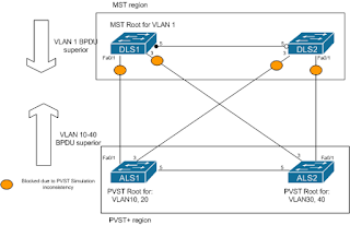
In the diagram, the MST region is root for VLAN1 (on switch DLS1), and is therefore trying to become root for all VLANs on its boundary ports. However, PVST+ has been configured to consider ALS1 as root bridge for VLANs 10 and 20, and ALS2 for VLANs 30 and 40. In this case, they are sending superior BPDUs for these VLANs to the MST boundary ports, which are then protecting the network by placing those ports into blocking state until the inconsistency is resolved.


An example of an error message on the console of DLS1 (a 3750) is shown below:
%SPANTREE-2-PVSTSIM_FAIL: Superior PVST BPDU received on VLAN 10 port Fa0/1, claiming root 4106:001b.0ddc.e580. Invoking root guard to block the port.

 This can be resolved in one of two ways:

  1. Change the VLAN 1 root bridge to either of the PVST+ bridges.
  2. Change the priority of VLANs 10 - 40 to be higher (inferior) to VLAN 1 on both the MST and PVST+ switches.

Monday, 6 July 2015

Spanning tree and superior BPDUs

SPANNING TREE SIMPLICITY

The bewilderment surrounding the Spanning Tree Protocol and root ports and designated ports (well it bewildered me anyway!) can be immensely simplified by one idea:
It's all about SUPERIOR BPDUs.

Superior BPDUs

So first of all, what is a superior BPDU? It's one that 'wins' i.e. is the LOWEST in the following ranking. If any one is a TIE, then the next lowest down is used to break that tie:
  1. Root Bridge ID (RBID)
  2. Root Path Cost (RPC)
  3. Sending Bridge ID (SBID)
  4. Sending Port ID (SPID)
  5. Receiving Port ID - only used is very rare cases and is not carried in the BPDU, it is assigned locally.
All the information in 1-4 above is carried (along with the timers) in every BPDU that is sent by every switch running STP.
So how does this help? It explains almost everything about the STP process and convergence, and helps, in my mind, to very succinctly define root port and designated port!

Convergence steps

To recap on the three fundamental steps that need to occur for STP convergence:

1) Elect a root bridge 2) Determine root ports 3) Determine designated ports

Elect a root bridge

Electing a root bridge is determined by the lowest RBID (i.e the superior one) in any BPDU circulating the network. It is determined to be a SUPERIOR BPDU because it has the lowest value in the first superiority criteria. Since the superior RBID is placed into all forwarded BPDUs during the election, thereafter EVERY BDPU WILL HAVE THE SAME RBID. So you can discount it!

Determine root ports

Determining the root port (RP) for any switch is done on the basis of lowest 'resulting' path cost (i.e. RPC in the BPDU + receiving port cost) to the root bridge, which is the SECOND SUPERIORITY CRITERIA. It makes sense that there can only be one lowest cost path to the RB from any other switch, and therefore that there can only be one RP per switch.

Now we already know that RBID is going to be the same in every BPDU, so what's next? Root Path Cost.

And the RP, therefore can be very simply defined as the ONLY port on the switch RECEIVING the SUPERIOR BPDU. There can only one port, because there can only be one superior BPDU. If RPC is a tie, then go to the next criteria, and so on. You also know that BPDUs are not sent out of RPs, because there would be no point. Why? Because you already know that the most superior BPDU on the segment ARRIVED on that port, and yours is sure to be ignored as inferior. Also the BPDU stored on a RP is always the superior one of any sent on the segment.

Determine designated ports

Similarly, the designated port (DP) is the only port on the SEGMENT that is SENDING the SUPERIOR BPDU. RPCs in the sent and received BPDUs are simply compared against each other, without modification. How does it know? Because it doesn't hear any that are superior. If it does, it knows it's not the DP, and stops sending them!  Again, because there can only be one superior BPDU on the segment, only one port can be sending it.

This means that ports that are not disabled and, although not connected to another switch, are participating in STP are also designated ports; hence they do not get put into blocking state.

A port that uses 'portfast' setting is a special case since it does not send BPDUs and therefore cannot really be considered a DP, but it is immediately placed into Forwarding state.

Monday, 29 June 2015

Some lab notes for Dynamic Trunking Protocol

Dynamic Trunking Protocol (DTP) Notes

Effect of 'switchport mode access' on DTP

After disabling DTP on all other ports, using 'switchport nonegotiate' and enabling 'debug dtp packets' I started investigating the effect of different port settings on DTP. I had been reading some discussion about whether an access port would still send out some DTP packets even after being turned into an access port using the 'switchport mode access' command.

So I put the port into dynamic desirable mode on both ends, successfully established a trunk, and then set one end as an access port.

Here are the results:

DLS2(config-if)#switchport mode access

DLS2(config-if)#

00:43:43: DTP-pkt:Fa0/5:Sending packet ../dyntrk/dyntrk_process.c:1241

00:43:43: DTP-pkt:Fa0/5: TOS/TAS = ACCESS/OFF ../dyntrk/dyntrk_process.c:1244

00:43:43: DTP-pkt:Fa0/5: TOT/TAT = ISL/NEGOTIATE ../dyntrk/dyntrk_process.c:1247

00:43:43: DTP-pkt:Fa0/5:datagramout ../dyntrk/dyntrkprocess.c:1279

00:43:43: DTP-pkt:Fa0/5:Invalid TLV (type 0, len 0) in received packet. ../dyntrk/dyntrk_core.c:1334

00:43:43: DTP-pkt:Fa0/5:Good DTP packet received: ../dyntrk/dyntrk_core.c:1500

00:43:43: DTP-pkt:Fa0/5: Domain: ../dyntrk/dyntrk_core.c:1503

00:43:43: DTP-pkt:Fa0/5: Status: TOS/TAS = ACCESS/DESIRABLE ../dyntrk/dyntrk_core.c:1506

00:43:43: DTP-pkt:Fa0/5: Type: TOT/TAT = ISL/NEGOTIATED ../dyntrk/dyntrk_core.c:1508

00:43:43: DTP-pkt:Fa0/5: ID: 000F90236585 ../dyntrk/dyntrk_core.c:1511

So we can see that only one final DTP packet is sent and received to advise that the port has been placed in Access mode. It then ignores any further DTP packets, even though I can see them still being sent from the other end if I disable and enable DTP by putting the port on the other end into access mode, then back to dynamic desirable.

'switchport nonegotiate' limitations

'switchport nonegotiate' cannot be configured on a port already configured as a DTP trunk i.e. dynamic desirable or dynamic auto. It doesn't just switch DTP off on the port; you would have to place the port into 'switchport mode access' or 'switchport mode trunk' first.

Trunk encapsulation negotiation

Manually setting encapsulation on one end of the link

When DTP is used to negotiate encapsulation ('switchport trunk encapsulation negotiate'), which is default, then the trunk will be negotiated, if both switches support it, as

  1. ISL, then
  2. 802.1q, if ISL is not supported by both switches.

However, even between two switches that support ISL, if encapsulation is set manually, using 'switchport trunk encapsulation isl | dot1q', at only one end, then DTP will negotiate that encapsulation on the link.

Limitations on the 'switchport mode trunk' command

The 'switchport mode trunk' command is used to manually set a link to always be a trunk. DTP packets are still sent out of the interface, so a trunk could still be formed with an 'active' DTP port.

However, the 'switchport mode trunk' command cannot be applied if encapsulation is negotiated. The encapsulation must be set manually.

DLS1(config-if)#switchport mode trunk

Command rejected: An interface whose trunk encapsulation is "Auto" can not be configured to "trunk" mode.

The error message is slightly misleading, referring to "Auto" encapsulation. This confused me the first time I saw it, until I realised it was referring to 'switchport trunk encapsulation negotiate' i.e. negotiated encapsulation. It would be great if Cisco kept their error messages consistent with their command syntax!

Sunday, 28 June 2015

Multi-Layer Switch: routed port, switchport and SVIs

'switchport'

The 'switchport' command tells the switch (usually a Multi-Layer Switch or MLS) to treat the port as a layer 2 port, i.e. as a member of a VLAN and to allow it to switch frames and learn MAC addresses etc., as well as participating in all other layer 2 processes such as spanning-tree.

'no switchport'

The 'no switchport' command tells the switch to treat the port as a layer 3 interface, so that you can run a routing protocol, add an interface IP address (or other layer 3 address) and create sub-interfaces, none of which is possible on a layer 2 interface. If you try running this command on a layer 2 only switch (e.g. a 2950) it will not understand it and reject it as 'incomplete', as shown below:
ALS1#conf t
Enter configuration commands, one per line. End with CNTL/Z.
ALS1(config-if)#no switchport
% Incomplete command.
A routed port does not belong to a VLAN as far as the MLS is concerned because it has no concept of VLANs at layer 3, just a like a port on a router. However, on a MLS each VLAN also has a layer 3 interface: the VLAN interface, also known as an SVI. This is created on an MLS when the VLAN itself is created.

On a pure layer 2 switch, such as the 2950, there is only one layer 3 interface: this is the 'VLAN1' interface (an SVI) that you configure to allow management connectivity.
ALS1#show run int vlan 1
Building configuration...
Current configuration : 67 bytes
!
interface Vlan1
no ip address
no ip route-cache
shutdown
end