MST and PVST+ interoperability
This confused me for quite some time, but turns out to be relatively simple, so I thought I would write a quick post about it.The case of MST interoperating with CST and RSTP is straightforward, since both type of spanning tree will have a single instance (IST in case of the MST process) with a single root etc. These can be used to interact and determine root bridge for the entire network (an extended single spanning-tree instance).
PVST+ interaction is more complex, since each VLAN has its own instance, each with potentially a different root bridge and spanning tree topology (which is kind of the point of the technology!) and determining port roles for boundary ports (i.e. the ports interconnecting the MST and PVST region) that is consistent for all VLANs is much more difficult.
First of all, VLAN 1's BPDUs are used to represent the entire PVST+ region, and IST (MST instance 0) repesents the MST region side using PVST Simulation.
PVST Simulation
MST uses PVST+ BPDUs to speak to all PVST+ instances, each containing the same IST information. This allows PVST+ to make a consistent choice about a port's role and state. IST also needs to be sure that VLAN 1's BPDUs represent the state for all VLANs in the PVST+ region.The port roles in MST - PVST+ boundary ports are: Designated, Root, and non-designated.
MST boundary Designated Port
An MST boundary port will become designated if BPDUs for VLAN 1 are superior to received PVST+ VLAN1 BDPUs.Also, to maintain PVST+ simulation consistency, all received BPDUs (i.e. for all VLANs) on an MST boundary DP must be inferior.
MST boundary Root Port
Keeping in mind that an MST region can be modeled as a single switch, it follows that for an MST boundary port to become a Root Port toward the CIST root bridge it must be receiving the superior VLAN1 BPDU of ANY MST region boundary port.Also, to maintain PVST+ simulation consistency, all received BPDUs for VLANs other than VLAN1 on an MST boundary RP must be identical or superior to those of VLAN1.
PVST Simulation Inconsistency
An inconsistency arises if the root bridge region for non-VLAN 1 instances is different to that of VLAN 1, which are indicated to the switch by the consistency criteria above.If the PVST Simulation consistency criteria are not met, then the port will be placed in a blocked state (designated PVST Simulation Inconsistent or Root Inconsistent) until the criteria are met.
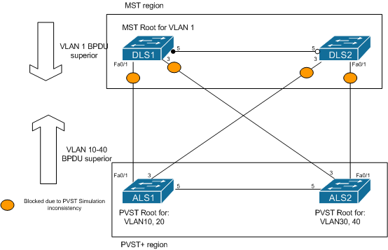
In the diagram, the MST region is root for VLAN1 (on switch DLS1), and is therefore trying to become root for all VLANs on its boundary ports. However, PVST+ has been configured to consider ALS1 as root bridge for VLANs 10 and 20, and ALS2 for VLANs 30 and 40. In this case, they are sending superior BPDUs for these VLANs to the MST boundary ports, which are then protecting the network by placing those ports into blocking state until the inconsistency is resolved.
An example of an error message on the console of DLS1 (a 3750) is shown below:
%SPANTREE-2-PVSTSIM_FAIL: Superior PVST BPDU received on VLAN 10 port Fa0/1, claiming root 4106:001b.0ddc.e580. Invoking root guard to block the port.
This can be resolved in one of two ways:
- Change the VLAN 1 root bridge to either of the PVST+ bridges.
- Change the priority of VLANs 10 - 40 to be higher (inferior) to VLAN 1 on both the MST and PVST+ switches.
No comments:
Post a Comment