Might follow this up with others for other headers / frame contents etc.
Saturday, 25 July 2015
IPv4 Header Game
I found a website that creates simple games, and I used it to make one [IPv4 Header game] to help with identification of fields in the IPv4 header.
Sunday, 19 July 2015
Multiple Spanning Tree and Cisco Per-VLAN Spanning Tree interactions
MST and PVST+ interoperability
This confused me for quite some time, but turns out to be relatively simple, so I thought I would write a quick post about it.The case of MST interoperating with CST and RSTP is straightforward, since both type of spanning tree will have a single instance (IST in case of the MST process) with a single root etc. These can be used to interact and determine root bridge for the entire network (an extended single spanning-tree instance).
PVST+ interaction is more complex, since each VLAN has its own instance, each with potentially a different root bridge and spanning tree topology (which is kind of the point of the technology!) and determining port roles for boundary ports (i.e. the ports interconnecting the MST and PVST region) that is consistent for all VLANs is much more difficult.
First of all, VLAN 1's BPDUs are used to represent the entire PVST+ region, and IST (MST instance 0) repesents the MST region side using PVST Simulation.
PVST Simulation
MST uses PVST+ BPDUs to speak to all PVST+ instances, each containing the same IST information. This allows PVST+ to make a consistent choice about a port's role and state. IST also needs to be sure that VLAN 1's BPDUs represent the state for all VLANs in the PVST+ region.The port roles in MST - PVST+ boundary ports are: Designated, Root, and non-designated.
MST boundary Designated Port
An MST boundary port will become designated if BPDUs for VLAN 1 are superior to received PVST+ VLAN1 BDPUs.Also, to maintain PVST+ simulation consistency, all received BPDUs (i.e. for all VLANs) on an MST boundary DP must be inferior.
MST boundary Root Port
Keeping in mind that an MST region can be modeled as a single switch, it follows that for an MST boundary port to become a Root Port toward the CIST root bridge it must be receiving the superior VLAN1 BPDU of ANY MST region boundary port.Also, to maintain PVST+ simulation consistency, all received BPDUs for VLANs other than VLAN1 on an MST boundary RP must be identical or superior to those of VLAN1.
PVST Simulation Inconsistency
An inconsistency arises if the root bridge region for non-VLAN 1 instances is different to that of VLAN 1, which are indicated to the switch by the consistency criteria above.If the PVST Simulation consistency criteria are not met, then the port will be placed in a blocked state (designated PVST Simulation Inconsistent or Root Inconsistent) until the criteria are met.
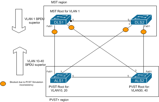
In the diagram, the MST region is root for VLAN1 (on switch DLS1), and is therefore trying to become root for all VLANs on its boundary ports. However, PVST+ has been configured to consider ALS1 as root bridge for VLANs 10 and 20, and ALS2 for VLANs 30 and 40. In this case, they are sending superior BPDUs for these VLANs to the MST boundary ports, which are then protecting the network by placing those ports into blocking state until the inconsistency is resolved.
An example of an error message on the console of DLS1 (a 3750) is shown below:
%SPANTREE-2-PVSTSIM_FAIL: Superior PVST BPDU received on VLAN 10 port Fa0/1, claiming root 4106:001b.0ddc.e580. Invoking root guard to block the port.
This can be resolved in one of two ways:
- Change the VLAN 1 root bridge to either of the PVST+ bridges.
- Change the priority of VLANs 10 - 40 to be higher (inferior) to VLAN 1 on both the MST and PVST+ switches.
Monday, 6 July 2015
Spanning tree and superior BPDUs
SPANNING TREE SIMPLICITY
The bewilderment surrounding the Spanning Tree Protocol and root ports and designated ports (well it bewildered me anyway!) can be immensely simplified by one idea:It's all about SUPERIOR BPDUs.
Superior BPDUs
So first of all, what is a superior BPDU? It's one that 'wins' i.e. is the LOWEST in the following ranking. If any one is a TIE, then the next lowest down is used to break that tie:- Root Bridge ID (RBID)
- Root Path Cost (RPC)
- Sending Bridge ID (SBID)
- Sending Port ID (SPID)
- Receiving Port ID - only used is very rare cases and is not carried in the BPDU, it is assigned locally.
So how does this help? It explains almost everything about the STP process and convergence, and helps, in my mind, to very succinctly define root port and designated port!
Convergence steps
To recap on the three fundamental steps that need to occur for STP convergence:1) Elect a root bridge 2) Determine root ports 3) Determine designated ports
Elect a root bridge
Electing a root bridge is determined by the lowest RBID (i.e the superior one) in any BPDU circulating the network. It is determined to be a SUPERIOR BPDU because it has the lowest value in the first superiority criteria. Since the superior RBID is placed into all forwarded BPDUs during the election, thereafter EVERY BDPU WILL HAVE THE SAME RBID. So you can discount it!Determine root ports
Determining the root port (RP) for any switch is done on the basis of lowest 'resulting' path cost (i.e. RPC in the BPDU + receiving port cost) to the root bridge, which is the SECOND SUPERIORITY CRITERIA. It makes sense that there can only be one lowest cost path to the RB from any other switch, and therefore that there can only be one RP per switch.Now we already know that RBID is going to be the same in every BPDU, so what's next? Root Path Cost.
And the RP, therefore can be very simply defined as the ONLY port on the switch RECEIVING the SUPERIOR BPDU. There can only one port, because there can only be one superior BPDU. If RPC is a tie, then go to the next criteria, and so on. You also know that BPDUs are not sent out of RPs, because there would be no point. Why? Because you already know that the most superior BPDU on the segment ARRIVED on that port, and yours is sure to be ignored as inferior. Also the BPDU stored on a RP is always the superior one of any sent on the segment.
Determine designated ports
Similarly, the designated port (DP) is the only port on the SEGMENT that is SENDING the SUPERIOR BPDU. RPCs in the sent and received BPDUs are simply compared against each other, without modification. How does it know? Because it doesn't hear any that are superior. If it does, it knows it's not the DP, and stops sending them! Again, because there can only be one superior BPDU on the segment, only one port can be sending it.This means that ports that are not disabled and, although not connected to another switch, are participating in STP are also designated ports; hence they do not get put into blocking state.
A port that uses 'portfast' setting is a special case since it does not send BPDUs and therefore cannot really be considered a DP, but it is immediately placed into Forwarding state.
Monday, 29 June 2015
Some lab notes for Dynamic Trunking Protocol
Dynamic Trunking Protocol (DTP) Notes
Effect of 'switchport mode access' on DTP
After disabling DTP on all other ports, using 'switchport nonegotiate' and enabling 'debug dtp packets' I started investigating the effect of different port settings on DTP. I had been reading some discussion about whether an access port would still send out some DTP packets even after being turned into an access port using the 'switchport mode access' command.
So I put the port into dynamic desirable mode on both ends, successfully established a trunk, and then set one end as an access port.
Here are the results:
DLS2(config-if)#switchport mode access
DLS2(config-if)#
00:43:43: DTP-pkt:Fa0/5:Sending packet ../dyntrk/dyntrk_process.c:1241
00:43:43: DTP-pkt:Fa0/5: TOS/TAS = ACCESS/OFF ../dyntrk/dyntrk_process.c:1244
00:43:43: DTP-pkt:Fa0/5: TOT/TAT = ISL/NEGOTIATE ../dyntrk/dyntrk_process.c:1247
00:43:43: DTP-pkt:Fa0/5:datagramout ../dyntrk/dyntrkprocess.c:1279
00:43:43: DTP-pkt:Fa0/5:Invalid TLV (type 0, len 0) in received packet. ../dyntrk/dyntrk_core.c:1334
00:43:43: DTP-pkt:Fa0/5:Good DTP packet received: ../dyntrk/dyntrk_core.c:1500
00:43:43: DTP-pkt:Fa0/5: Domain: ../dyntrk/dyntrk_core.c:1503
00:43:43: DTP-pkt:Fa0/5: Status: TOS/TAS = ACCESS/DESIRABLE ../dyntrk/dyntrk_core.c:1506
00:43:43: DTP-pkt:Fa0/5: Type: TOT/TAT = ISL/NEGOTIATED ../dyntrk/dyntrk_core.c:1508
00:43:43: DTP-pkt:Fa0/5: ID: 000F90236585 ../dyntrk/dyntrk_core.c:1511
So we can see that only one final DTP packet is sent and received to advise that the port has been placed in Access mode. It then ignores any further DTP packets, even though I can see them still being sent from the other end if I disable and enable DTP by putting the port on the other end into access mode, then back to dynamic desirable.
'switchport nonegotiate' limitations
'switchport nonegotiate' cannot be configured on a port already configured as a DTP trunk i.e. dynamic desirable or dynamic auto. It doesn't just switch DTP off on the port; you would have to place the port into 'switchport mode access' or 'switchport mode trunk' first.
Trunk encapsulation negotiation
Manually setting encapsulation on one end of the link
When DTP is used to negotiate encapsulation ('switchport trunk encapsulation negotiate'), which is default, then the trunk will be negotiated, if both switches support it, as
- ISL, then
- 802.1q, if ISL is not supported by both switches.
However, even between two switches that support ISL, if encapsulation is set manually, using 'switchport trunk encapsulation isl | dot1q', at only one end, then DTP will negotiate that encapsulation on the link.
Limitations on the 'switchport mode trunk' command
The 'switchport mode trunk' command is used to manually set a link to always be a trunk. DTP packets are still sent out of the interface, so a trunk could still be formed with an 'active' DTP port.
However, the 'switchport mode trunk' command cannot be applied if encapsulation is negotiated. The encapsulation must be set manually.
DLS1(config-if)#switchport mode trunk
Command rejected: An interface whose trunk encapsulation is "Auto" can not be configured to "trunk" mode.
The error message is slightly misleading, referring to "Auto" encapsulation. This confused me the first time I saw it, until I realised it was referring to 'switchport trunk encapsulation negotiate' i.e. negotiated encapsulation. It would be great if Cisco kept their error messages consistent with their command syntax!
Sunday, 28 June 2015
Multi-Layer Switch: routed port, switchport and SVIs
'switchport'
The 'switchport' command tells the switch (usually a Multi-Layer Switch or MLS) to treat the port as a layer 2 port, i.e. as a member of a VLAN and to allow it to switch frames and learn MAC addresses etc., as well as participating in all other layer 2 processes such as spanning-tree.'no switchport'
The 'no switchport' command tells the switch to treat the port as a layer 3 interface, so that you can run a routing protocol, add an interface IP address (or other layer 3 address) and create sub-interfaces, none of which is possible on a layer 2 interface. If you try running this command on a layer 2 only switch (e.g. a 2950) it will not understand it and reject it as 'incomplete', as shown below:ALS1#conf tA routed port does not belong to a VLAN as far as the MLS is concerned because it has no concept of VLANs at layer 3, just a like a port on a router. However, on a MLS each VLAN also has a layer 3 interface: the VLAN interface, also known as an SVI. This is created on an MLS when the VLAN itself is created.
Enter configuration commands, one per line. End with CNTL/Z.
ALS1(config-if)#no switchport
% Incomplete command.
On a pure layer 2 switch, such as the 2950, there is only one layer 3 interface: this is the 'VLAN1' interface (an SVI) that you configure to allow management connectivity.
ALS1#show run int vlan 1
Building configuration...
Current configuration : 67 bytes
!
interface Vlan1
no ip address
no ip route-cache
shutdown
end
Thursday, 25 June 2015
Private VLAN summary
Private VLANs
Allows for the separation of ports into private port groups, while still making use of the same subnet. This is more efficient in terms of IP addressing usage and STP and ACL complexity and of particular use in some shared environments such as Service Provider (SP) data centres where access to common resources on a subnet are required in a secure way.There are essentially three different port classifications in terms of function. Ports that need to communicate with:
- all devices
- each other and with shared devices (e.g. router or web server)
- ONLY shared devices
Private VLANs are only supported by VTPv3, so "VTP transparent" mode should be configured if not using VTPv3.
Primary VLANs
Contains promiscuous ports i.e. can send and receive to any other port in the PVLAN including those assigned to secondary VLANs. Devices in this VLAN are likely to include the router L3 gateway, web servers, database servers etc.Secondary VLANs
Are one of two types Community or IsolatedCommunity VLANs
- Ports can talk to other ports in the community and to primary VLAN (promiscuous) ports
- Each PVLAN has zero or more community VLANs associated with it.
Isolated VLANs
- Ports can ONLY talk to primary VLAN (promiscuous) ports
- Each PVLAN has AT MOST ONE isolated VLAN, since only one is required
Private VLAN trunks
Extending Private VLANs across multiple switches is a simple matter; simply use the same VLAN IDs and trunk the VLANs as you would normally. Frames arriving from a port within a Private VLAN (primary or secondary) are tagged with the primary or secondary VLAN tag for transport between switches.However, there are two special trunk types that are used with Private VLANs:
Promiscuous PVLAN Trunk
This is used when a trunk is carrying traffic for a Primary VLAN, as well as its associated secondaries, and needs to be considered a promiscuous port. It may also be carrying other normal VLANs. In this case, the device on the other end of the trunk is unaware of the relationship between the Private VLANs, and traffic from all secondary VLANs associated with a Primary VLAN is tagged with the Primary VLAN ID. A use case for this scenarios is a "router on a stick" configuration where the gateway interface of a Primary VLAN (on he router) is considered promiscuous and allowed to be communicated with my all associated Secondary VLANs.The Promiscuous PVLAN Trunk port re-writes secondary VLAN IDs of sent frames into the corresponding primary VLAN ID so that the external device always sees only the primary VLAN. It does not manipulate tags of incoming frames.
Isolated PVLAN Trunk
This is used to extend the isolated VLAN over a trunk carrying multiple VLANs to a switch that does not support Private VLANs but is capable of isolating its own ports e.g. with the port protection feature on entry-level Catalyst switches.The Isolated PVLAN Trunk re-writes a primary VLAN ID of a sent frame to the ID of the isolated VLAN that is associated with the primary VLAN. It does not manipulate tags of incoming frames.
Tuesday, 23 June 2015
Dangers of Tunnel vision
I gave myself a real fright today.
I was trying to troubleshoot an issue with a configuration that I've never done before; IPv6 ISIS. It was while I was on a training course, I was trying to do some route summarisation. and I struggled with the lab for about 45 minutes, taking out configuration, checking the routing table, putting it back in, checking it again. The topology was about as simple as you can get; two routers. And I checked and double-checked my configuration and found a little error and that made a difference but not the one I wanted.
Over and over and over again I looked at the routing table.
Except...
That is wasn't the full routing table. I was just looking at the ISIS routes. And as soon as the instructor made one little suggestion I looked at the WHOLE routing table, and there was the route... advertised by another protocol with a lower AD! Hidden in the trees, was the wood!
It turned my blood to ice to realise how easily I fell into the tunnel-vision trap - forgetting to take a pause and a step back; to think about alternatives. So that's why I'm writing about it today. If I read this again in 6-9 months' time I can remember today, and the fear I felt when I thought about how easily that could have happened to me in a lab exam, and how I would have totally blown it.
A long way to go, but food for thought.
Subscribe to:
Posts (Atom)